


联系我们
021-5076-3702
- 地址:
- 上海市闵行区浦江镇立民村立民路四组仓库
- 邮箱:
- 2012business@shanyu-valve.com
- 电话:
- 021-50763702
- 传真:
- 021-50853712
- 手机:
- 13816506689
产品介绍
参数Parameter| 公称通径Nominal diameter | 15-100mm | |
| 公称压力Nominal pressure | 150psi | |
| 适用温度Applicable temperature | 0-+60℃ | |
| 连接方式Connection mode | 由令、法兰 union、flange | |
| 适用介质Applicable medium | PVC兼容的食品工业化学溶剂Foodindustrialchemical solvent PVC compatible | |
| NO. | 部件名称 PART NAME | 材料 MATERIAL |
| 1 | 阀体 BODY | PVC-C/PP/PVDF |
| 2 | 阀杆O形圈 STEM O-RING | EPDM,FPM |
| 3 | 阀杆 STEM | PVC-C/PP/PVDF |
| 4 | 球体 BALL | PVC-C/PP/PVDF |
| 5 | 密封座 SEAT SEAL | PTFE |
| 6 | 托座密封圈 CARRIER O-RING | EPDM,FPM |
| 7 | 球体托座 SUPPORT FOR BALL SEAT | PVC-C/PP/PVDF |
| 8 | 由令密封圈 UNION O-RING | EPDM,FPM |
| 9 | 端接头 END CONNECTOR | PVC-C/PP/PVDF |
| 10 | 由令套 UNION NUT | PVC-C/PP/PVDF |
| 11 | 手柄 HANDLE | PP |
| 12 | 内埋螺母 INSERTED NUT | 不锈钢STAINLESS STEEL |
| 13 | 法兰片 FLANGE | PVC-C/PP/PVDF |
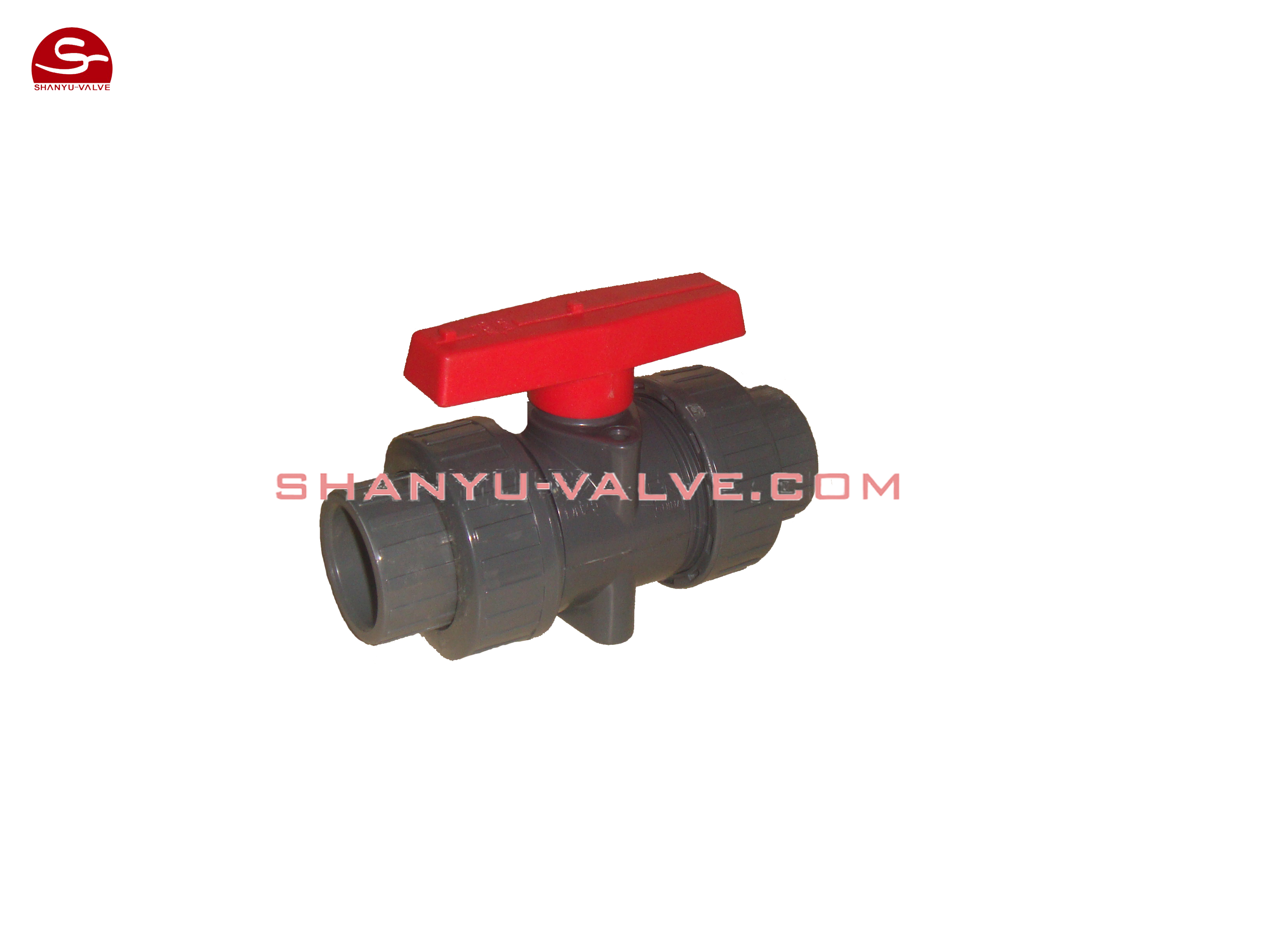
手动塑料球阀是一种比较新型的球阀类别,它有着自身结构所独有的一些优越性,如开关无摩擦,密封不易磨损,启闭力矩小。这样可减小所配执行器的规格。配以多回转电动执行机构,可实现对介质的调节和严密切断。广泛适用于石油、化工、城市给排水等要求严格切断的工况。手动球阀在管路中主要用来做切断、分配和改变介质的流动方向。
Manual plastic ball valve is a new type of ball valve type, it has some advantages of the unique structure of its own,such as the switch without friction, seal is not easy to wear, hoist torque small. This reduces the actuator withthe specifications. With multi turn electric actuator, which can be realized on the media regulation and tight shutoff.Widely used in petroleum, chemical industry, city water supply and drainage are strict cut-off conditions. The direction of the flow valve in the pipeline is mainly used tomake cutting, changes in media distribution.
规格示例图series specifications example in Figure

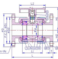
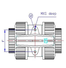
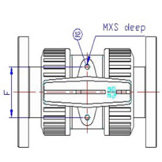
尺寸表Size table
|
SIZE NOM |
1/2" 15mm |
3/4" 20mm |
1" 25mm |
1-1/4" 32mm |
1-1/2" 40mm |
2" 50mm |
2-1/2" 65mm |
3" 80mm |
4" 100mm |
||
|
-法 兰 连 接 |
DIN | D | 95 | 105 | 115 | 140 | 150 | 165 | 185 | 200 | 220 |
| D1 | 65 | 75 | 85 | 100 | 110 | 120 | 145 | 163 | 180 | ||
| L | 130 | 150 | 160 | 180 | 200 | 230 | 290 | 310 | 350 | ||
| n-Øe | 4-14 | 4-14 | 4-14 | 4-18 | 4-18 | 4-18 | 4-18 | 8-18 | 8-18 | ||
| ANSI | D | 89 | 98 | 108 | 117 | 127 | 152 | 178 | 191 | 229 | |
| D1 | 61 | 70 | 79 | 89 | 99 | 121 | 140 | 152 | 191 | ||
| L | 143 | 172 | 187 | 190 | 212 | 234 | 259 | 304 | 372 | ||
| n-Øe | 4-16 | 4-16 | 4-16 | 4-16 | 4-16 | 4-19 | 4-19 | 4-19 | 8-19 | ||
|
由 令 连 接 |
DIN | Ød1 | 20.3 | 25.3 | 32.3 | 40.3 | 50.3 | 63.3 | 75.3 | 90.3 | 110.4 |
| Ød2 | 20.1 | 25.1 | 32.1 | 40.1 | 50.1 | 63.1 | 75.1 | 90.1 | 110.1 | ||
| I | 16 | 19 | 22 | 26 | 31 | 38 | 44 | 51 | 61 | ||
| L | 112 | 132 | 144 | 167 | 172 | 206 | 273 | 303 | 333 | ||
| ANSI | Ød1 | 21.54 | 26.87 | 33.65 | 42.42 | 48.56 | 60.63 | 73.38 | 89.31 | 114.76 | |
| Ød2 | 21.23 | 26.57 | 33.27 | 42.04 | 48.11 | 60.17 | 72.85 | 88.7 | 114.07 | ||
| I | 22.22 | 25.4 | 28.58 | 31.75 | 34.93 | 38.1 | 44.45 | 47.63 | 57.15 | ||
| L | 112 | 132 | 144 | 167 | 172 | 206 | 273 | 303 | 333 | ||
| ØD2/ØD | 45 | 55 | 66 | 82 | 98 | 120 | 140 | 163 | 225 | ||
| ØD1 | 31 | 37 | 44 | 54 | 65 | 79 | 92 | 108 | 146 | ||
| Ød | 13 | 18 | 23 | 30 | 38 | 48 | 61 | 69 | 99 | ||
| L1 | 60 | 73 | 78 | 87 | 92 | 112 | 136 | 158 |
176 |
||
上一篇:燃气专用阀